
Machine tool accuracy measurement is the process of quantifying how far a machine’s actual motion deviates from its commanded motion, so those deviations can be corrected through calibration or compensation. For precision and ultra-precision work, the geometry of every axis, the heat the machine generates, and the vibration around it all shift the cutting point by micrometers. This guide explains the geometric errors you need to capture, the methods used to measure them, the equipment involved, and the inspection workflow that turns raw data into reliable compensation values.
Table of Contents
- What is machine tool accuracy measurement?
- Why accuracy measurement matters
- The geometric errors to capture
- Key measurement methods
- Thermal and vibration error measurement
- The inspection workflow
- Equipment and environment setup
- FAQ
- Conclusion
What is machine tool accuracy measurement?
Machine tool accuracy measurement identifies and quantifies the error sources that separate a machine’s real tool path from its programmed path. Built on multi-body kinematics, it treats the machine as a chain of moving bodies and isolates the geometric, thermal, and dynamic errors contributed by each axis and joint. The output is a traceable dataset that feeds software error compensation and maintenance decisions, rather than a simple pass or fail verdict. This is also the foundation of any serious CNC machine accuracy testing program.
Why accuracy measurement matters
Tolerances in modern machining are unforgiving. Precision work typically targets deviations around ≤1µm, and ultra-precision work pushes toward ≤0.1µm. At that scale, an uncalibrated axis or an unmonitored heat source will produce parts that drift out of specification without any obvious cause. Disciplined machine tool calibration converts these hidden errors into measured, repeatable numbers you can compensate for in the controller. The result is higher first-pass yield, traceable quality records, and early warning before accuracy quietly decays. Machine tool geometric error measurement is the part of that effort that addresses the static geometry of the axes.
The geometric errors to capture
A three-axis machine has *21 geometric errors*. Each linear axis carries six degrees of freedom: one positioning (linear) error, two straightness errors, and three angular errors (pitch, yaw, and roll). Across the X, Y, and Z axes that is 18 errors, plus 3 squareness (perpendicularity) errors between the axis pairs, giving 21 in total. This 21-error model is well established in the measurement literature and aligns with the geometric tests defined in ISO 230-1.
Rotary axes add a further 6 errors per axis — positioning, two radial and one axial motion errors, and two tilt errors — assessed under the framework of ISO 230-7. Capturing all 27 error components for a machine with one rotary axis is what makes full compensation possible.
Key measurement methods
9-line and 12-line methods
For the translational axes, the 9-line and 12-line methods are two practical approaches. The 9-line method suits cases where displacement and straightness must be measured together: after confirming the axis topology (for example, a three-axis FXYZ configuration), nine measurement lines are planned, three per axis, and the 21 geometric errors are solved from the resulting system of linear equations, with squareness derived from straightness deviation over the guideway length.
The 12-line method applies when only displacement is measured. Twelve lines, including three diagonal lines, all starting from the origin, cover the full travel. Positioning error is read directly, angular errors come from displacement differences between parallel lines, and straightness is fitted by integration and least-squares. Each line is measured three times and averaged to suppress noise.
Rotary-axis errors
Rotary-axis geometric error measurement starts by mounting a standard mandrel on the axis centerline with coaxiality held to ≤0.002mm. Radial run-out is read on two parallel planes 100mm apart, axial run-out captures center-line displacement, and a precision indexing table compares commanded versus actual rotation. The individual error components are then separated from these readings.
Laser interferometer setup

A laser interferometer is the reference instrument for laser interferometer machine tool measurement of linear positioning and straightness. The laser source, beam splitter, and reflector establish an optical baseline along the axis; as the carriage moves, the interferometer reads sub-micrometer displacement directly against that baseline. A clear, unobstructed beam path and an environment free of strong electromagnetic interference are prerequisites for trustworthy readings.
Thermal and vibration error measurement
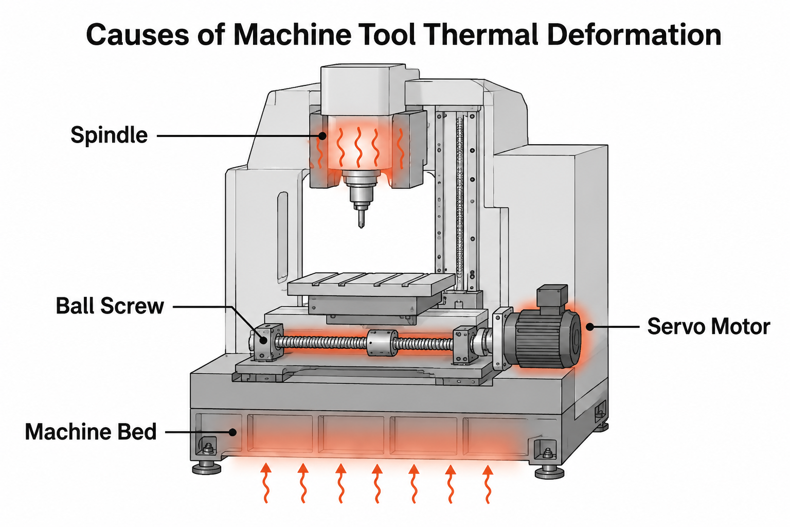
Geometry is only part of the story. Temperature sensors accurate to roughly ±0.01℃ are placed on the spindle, ball screw, and bed to record how temperature relates to deformation, with studied environmental swings in the ±0.1℃ to ±0.5℃ range. Under no-load and loaded conditions, temperature data is logged alongside geometric distortion measured by the interferometer to build a thermal error model. Thermal behavior is formally assessed under ISO 230-3, the part of the ISO 230 series covering thermal effects on machine tools. On the dynamic side, accelerometers check spindle and table vibration frequency and amplitude to judge dynamic balance, while a vibration test instrument monitors floor vibration, typically against a limit around ≤0.001g.
The inspection workflow
A repeatable inspection workflow moves through four stages, from preparation to verification.
flowchart LR
    A[Preparation<br/>environment, warm-up, calibration] --> B[Error detection<br/>geometric, thermal, vibration]
    B --> C[Data processing<br/>error identification and validation]
    C --> D[Result verification<br/>compare to design standards]
During data processing, errors are separated and solved, then validated: agreement between the 9-line and 12-line results should stay within ≤10%, and repeat measurements on the same line within ≤±0.2µm. Result verification compares each value against example design targets such as ≤3µm positioning error, with straightness held to tight per-metre limits that depend on the machine. Correlation analysis then attributes causes — for instance, flagging cases where thermal error accounts for more than 25% of the total.
Equipment and environment setup
The instrument set and conditions matter as much as the method. The environment is normally controlled to 21±0.5℃ with 40–60% relative humidity, with the machine cleaned and run unloaded for about 30 minutes to warm up before data is taken. Note that ISO 1 sets 20°C as the standard reference temperature for dimensional specification, so measurements should be related back to that baseline.
| Equipment | Purpose |
|---|---|
| Laser interferometer | Linear positioning, straightness, and angular error measurement |
| Temperature sensors | Thermal monitoring of spindle, ball screw, and bed |
| Accelerometers | Spindle and table vibration analysis |
| Vibration test instrument | Floor and environmental vibration monitoring |
| Precision indexing table | Rotary-axis rotation error reference |
| Standard mandrel | Rotary-axis run-out setup |
FAQ
How many geometric errors does a 3-axis machine tool have?
A three-axis machine has 21 geometric errors: 18 from the six degrees of freedom on each of the three linear axes (one positioning, two straightness, three angular), plus three squareness errors between the axis pairs. Each rotary axis adds six more.
What is the difference between the 9-line and 12-line methods?
The 9-line method measures displacement and straightness together across nine lines, which suits full geometric identification. The 12-line method measures displacement only across twelve lines, including three diagonals, and derives angular and straightness errors by calculation. Choose the 9-line method when you need direct straightness data, and the 12-line method when displacement capture is the priority.
Why does temperature control matter in accuracy measurement?
Thermal drift moves the machine’s geometry while you measure it, so unstable temperature corrupts the data. Controlling the environment and letting the machine reach a stable state ensures the recorded errors reflect true geometry rather than transient expansion, keeping results traceable to a reference temperature.
Conclusion
Reliable machine tool accuracy measurement combines a complete error model, the right methods for translational and rotary axes, controlled conditions, and a disciplined workflow that ends in verified, compensable data. Done well, it turns invisible micrometer-scale errors into numbers your controller and maintenance plan can act on. If you are specifying a new machine, planning a calibration program, or working through a precision-machining requirement, contact UBright with your drawings and accuracy targets and our team can help you plan the right inspection and compensation approach.
References
- ISO 230-1:2012 — Test code for machine tools, Part 1: Geometric accuracy — Supports the geometric accuracy test framework for positioning, straightness, and angular errors of linear axes.
- ISO 230-7:2015 — Test code for machine tools, Part 7: Geometric accuracy of axes of rotation — Supports the rotary-axis geometric error framework.
- ISO 1:2022 — Standard reference temperature for the specification of geometrical and dimensional properties — Supports the 20°C reference temperature baseline.
- Efficient Method for Identifying Key Errors Based on 21-Geometric-Error Measurement of Three Linear Axes (Applied Sciences, MDPI) — Supports the 21-geometric-error model of three linear axes.